Traceroute Guide
This guide contains all the knowledge you need to complete Project 1A and Project 1B.
This guide doesn’t depend on any previous lectures, though Lectures 1–4 (introduction lectures) may be helpful.
Here is a slideshow version of this guide.
1. Networking Background
1.1. Protocols
In this class, much of our focus will be on protocols that specify how machines exchange in communication. What is the format of the messages they exchange, and how do they respond to those messages?
Everybody using the protocol needs to agree on how the data is formatted, and what they should do in response to different messages.
As an analogy, consider a protocol for asking a question in class. First, you should raise your hand. You should wait for the teacher to call on you before you say your question. If the teacher doesn’t call on you, you could say “Excuse me!” to get their attention.
Here’s an example of a protocol. Alice and Bob both say hello, then Alice requests a file, and Bob replies with the file. To define this protocol, we need to define syntax (e.g. how to write “give me this file” in 1s and 0s), and semantics (e.g. Alice must receive a hello from Bob before requesting a file).
Different protocols are designed for different needs. For example, if Alice needs to get the file as quickly as possible, we might design a protocol without the initial hello messages.
Designing a good protocol can be harder than it seems! We might also need to account for edge cases, bugs, and malicious behavior. For example, what if Alice requests a file, and Bob replies with hello? How should Alice respond?
1.2. Building the Internet
To design the Internet, let’s think about the postal system as an analogy. How do we design the postal system?
Building block 1: We need some physical technology to move data across space. It could be a mailman walking, a mail truck, an airplane, the Pony Express, carrier pigeons, etc.
Similarly, in the Internet, we need some physical technology to move bits across space. It could be voltages on an electrical wire, light signals on an optical fiber, wireless radio waves, etc.
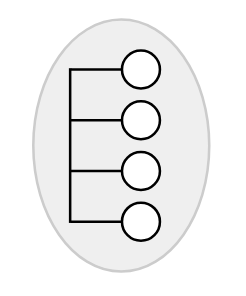
Building block 2: Using our physical technology, we can create links to connect everybody in the local town.
Similarly, in the Internet, we can use our physical technology to link up everybody in a local area.
Building block 3: What if we wanted to connect houses in different towns? We could create direct links between every pair of houses, but this is expensive.
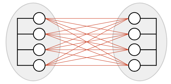
Instead, we could introduce a post office in each town. Now, we just need a single cross-town link to connect the two post offices.
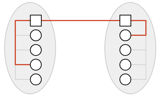
If I’m in Oakland, and I want to send mail to you in Berkeley: I send my letter to the Oakland post office. The Oakland post office forwards the letter to the Berkeley post office. Finally, the Berkeley post office forwards the letter to you.
With enough post offices, we can connect all the towns in the world!
1.3. Properties of the Internet
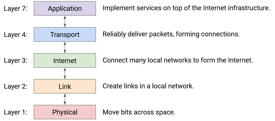
Notice that our design decomposed the system into layers of abstraction. Each layer relies on services from the layer below. Each layer then provides its services to the layer above.
Layer 1 (Physical) moves bits across space.
Layer 2 (Link) creates links in a local network. Layer 2 relies on the technology we built at Layer 1.
Layer 3 (Internet) connects up local networks to form the Internet. Layer 3 relies on the local networks we built at Layer 2.
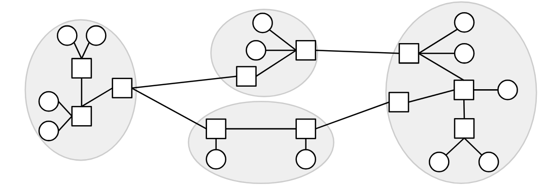
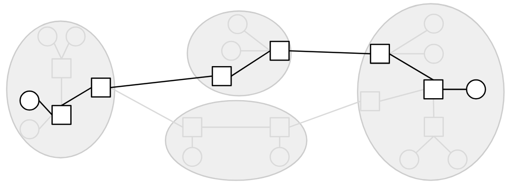
The Internet is often called a “network of networks.” Each operator runs its own local network (think of it like a small town). Then, the local networks connect to each other to form the Internet.
There are two types of machines on the Internet:
End hosts are the machines actually talking to each other (e.g. your laptop, your phone, Google’s web server). In the analogy, these are the houses. We usually draw end hosts as circles.
Routers (also known as switches) are the machines that receive messages and forward them toward their destination. In the analogy, these are the post offices. We usually draw routers as squares.
In our model, a link connects two machines. However, the source and destination are not necessarily directly connected with a link.
Instead, a message can take multiple hops to reach the destination. When a router receives a message, it must forward the message closer to its final destination.
For now, we won’t discuss how the routers figure out where to forward the messages. Though, do note that if you send a bunch of messages to the same destination, they’re not all guaranteed to take the same path.
The Internet only offers best-effort service. This means that messages could get lost, reordered, corrupted, etc. The network will try its best to deliver your message, but there are no guarantees.
If we want something better than best-effort, we’ll have to build more layers.
1.4. Higher Layers
Layer 4 (Transport) adds extra features (e.g. re-sending lost messages) to guarantee reliable delivery. Layer 4 also provides a feature called ports (discussed further below). Layer 4 relies on the best-effort global delivery that we built at Layer 3.
Layer 7 (Application) is where we build actual programs that use the Internet. It relies on the features (reliability, ports) we built at Layer 4.
In this project, our main focus will be at Layer 3 (Internet) and Layer 4 (Transport).
1.5. Headers
Suppose A wants to send a message to B.
A takes the bits of the message and transmits them to the next router along the path. The router has no idea what to do with these packets!
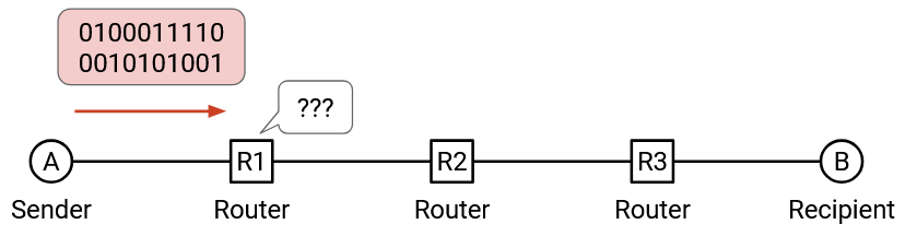
When we send a message, we need to include some metadata, so that the intermediate routers and the recipient know what to do with the bits they receive.
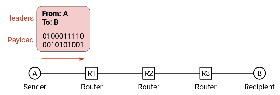
In the postal analogy: We have to put the letter in an envelope. The envelope describes what to do with the letter.
The main unit of data on the Internet is a packet. A packet contains a header with metadata about the message, followed by a payload containing the message itself.
What metadata goes in the header?
We have to include the destination address, so that the packet can be delivered to the correct recipient.
We often also include the source address, in case the recipient wants to send replies back.
For this project, we won’t discuss where these addresses come from. We’ll magically assume that all machines have unique IP addresses, which are written as four numbers separated by dots (e.g. 3.3.3.3).
Machines also have human-readable names like www.berkeley.edu, and you might see them in the project sometimes. For this project, we won’t discuss where these names come from. We’ll magically assume that everyone can convert between names and addresses as needed (check out DNS if you want a preview).
1.6. Multiple Headers
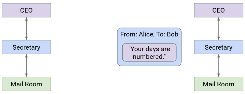
Let’s go back to the postal analogy briefly. Suppose the boss of Company A wants to write a letter to the boss of Company B. How does the message get sent?
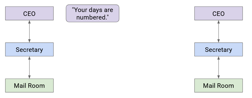
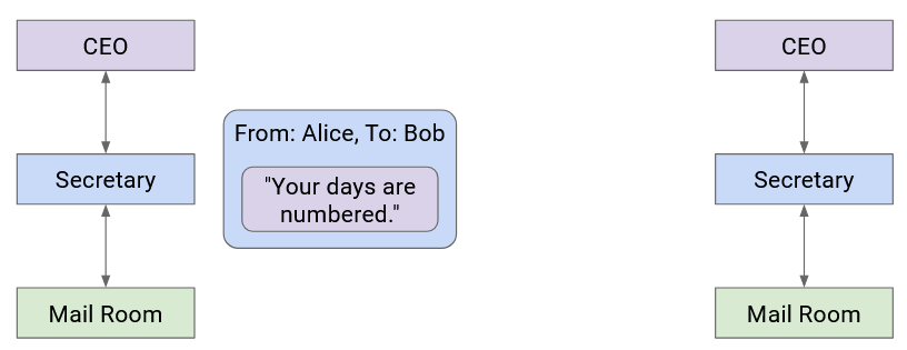
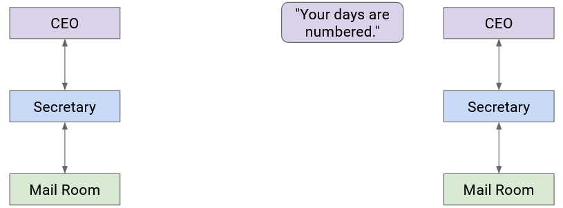
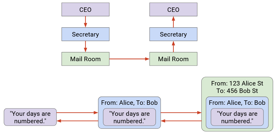
Company A’s boss folds the letter and hands it to their secretary. Then, the secretary puts the letter in an envelope with Company B’s boss’s full name.
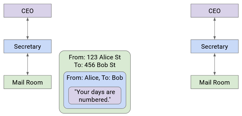
The secretary passes this letter to the mailroom. The postal worker puts the letter in a box with Company B’s street address on it, and puts the package in a delivery truck.
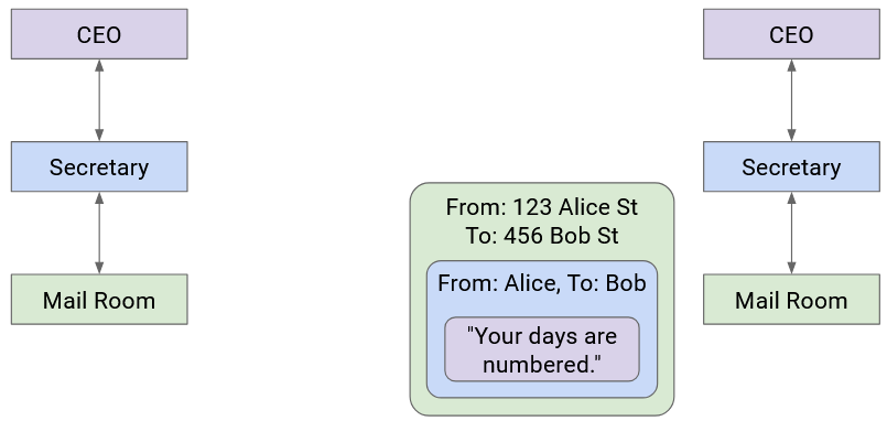
At this point, the letter itself is wrapped in multiple layers of identifying information (envelope, box). The delivery company sends the letter to Company B (possibly across several trucks, planes, mailmen, etc.).
When the letter reaches Company B, the mailroom removes the box and passes the envelope to the secretary.
Then, the secretary sees the boss’s name on the envelope, removes the envelope, and passes the letter up to the Company B boss.
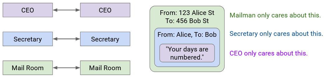
Notice that as we moved to lower abstraction layers, we wrapped more headers around the data. Then, as we moved to higher abstraction layers, we peeled layers off the data.
Each layer only has to understand its own header, and is “communicating” (in some sense) with its peers at the same layer. When Secretary A writes the name on the envelope, that’s meant for Secretary B to read (not the mailmen, or the boss).
More formally, on the Internet, peers at the same layer communicate by establishing a protocol at that layer. The protocol only makes sense to entities at that specific layer.
In this project, our main focus will be the Layer 3 (Internet) and Layer 4 (Transport) headers.
This means that our packets will have an outer, lower-layer header (e.g. Layer 3), and an inner, higher-layer header (e.g. Layer 4).
1.7. Demultiplexing
As long as the sender and recipient both agree on the stack of protocols being used, they can choose whatever stack of protocols they want (generally one per layer).
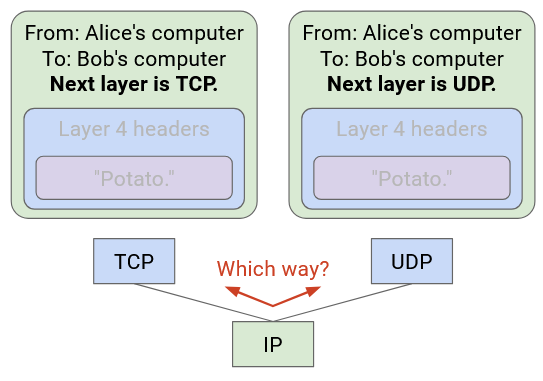
When the recipient gets the packet, it must unwrap the headers, passing the packet up through higher-layer protocols.
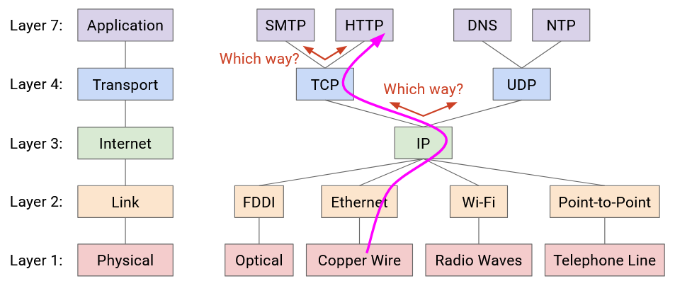
How did IP know to pass the packet to the TCP code, not the UDP code?
How did TCP know to pass the packet to the HTTP code, not the SMTP code?
To solve this problem, we will add an additional header field for demultiplexing. This header field tells us what the next higher-layer protocol is. In other words, it tells us what protocol we should use to parse the remaining payload, after we strip away our layer’s header.
1.8. Demultiplexing with Ports
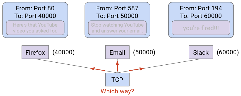
Demultiplexing also works at Layer 4.
Each running application on your computer is associated with a port number.
When the Layer 4 protocol receives a packet, it uses the port number to pass the packet to the corresponding application.
In the postal analogy: Imagine if you and your housemate both have the street address. If someone sends a letter to your house, is it for you or your housemate? We can distinguish by assigning room numbers to each housemate.
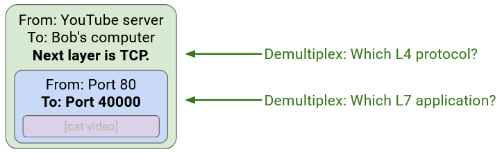
Note that demultiplexing can work at both Layer 3 and Layer 4. In the outer Layer 3 header, we write which Layer 4 protocol is up next. Then, in the inner Layer 4 header, we write which application is up next.
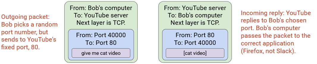
Note that if two applications are exchanging messages back-and-forth, both applications have a port number.
Recall that Layer 4 can be used to implement different features, such as demultiplexing and reliability. Different protocols offer different features.
In this project, we’ll use UDP (User Datagram Protocol) as our Layer 4 protocol. UDP offers demultiplexing with ports, but it does not offer reliability.
Disclaimer: In networking, there are two different things, both called “ports.” We just saw logical ports, which are numbers used to identify applications in software. There’s a naming conflict with physical ports, which are the holes you plug a cable into. In this project, we’ll mainly deal with logical ports (and will clarify if it’s unclear).
2. Introducing Traceroute
2.1. Time-to-Live (TTL)
Routers on the Internet can be buggy.

Suppose you want to send packets to 5.5.5.5.
You forward the packet to 2.2.2.2.
Then, 2.2.2.2 decides to forward the packet to 3.3.3.3.
Now, imagine 3.3.3.3 and 4.4.4.4 are buggy routers. 3.3.3.3 sends the packet to 4.4.4.4, which sends the packet back to 3.3.3.3, which sends the packet back to 4.4.4.4, and so on. Our packet is trapped in an infinite loop!
It would be a waste of resources if 3.3.3.3 and 4.4.4.4 kept forwarding the same packet forever.
To solve this problem, we’ll add an extra header in the Layer 3 (IP) header, called the time-to-live (TTL). The TTL imposes a maximum number of hops that a packet can take before it expires.
When a router receives a packet, it first decrements the TTL (modifying the header) before forwarding the packet.
If you receive a packet with a TTL of 1, you’ll modify the header and reach a TTL of 0. This means that the packet has expired, so you should drop the packet (ignore it and don’t forward it).
When a router receives an expired packet, it should also send an error message back to the original sender, so that the sender knows that their packet was dropped.
2.2. Exploiting TTL
Normally, if you send a packet and receive a response packet, you don’t know what path the packets used to travel through the network. In other words, you can’t figure out which intermediate routers forwarded your packet. None of the header fields tell you about the path the packet used.
Can you think of a way to exploit the TTL field to discover the routers along the path between you and a specific destination?
Manul zone. You may stare at the manul while you think about the question. The manul requests that you don’t scroll to see the answer until you’ve given it some deep thought.

End of the manul zone.
The key realization is: If we set the TTL low enough, the packet will expire before reaching the destination. When the packet expires, the router will send you an error message. The error message header will say: “From router, to you.” This allows you to discover a router along the path to the destination!
The traceroute utility tries to discover all the routers along the path between you and a specified destination, by sending packets with successively higher TTLs.
At a high level, traceroute works like this:

Send a packet to the destination, with TTL 1. This will reach the first router and expire there. The first router (1.1.1.1) will send you an error message, which lets you discover the first router.
Send a packet to the destination, with TTL 2. This will reach the second router and expire there. The second router (2.2.2.2) will send you an error message, which lets you discover the second router.
Send a packet to the destination, with TTL 3. This will reach the third router (3.3.3.3) and expire there. The third router will send you an error message, which lets you discover the third router.
Notice that every packet you send is intended for the specified destination. You’re never sending packets intended for intermediate routers (since the whole point of traceroute is, you don’t know who those routers are).
The packets we send are UDP-over-IP packets. By contrast, the routers’ error messages are ICMP-over-IP packets. The ICMP protocol has a different header structure, which allows the router to encode the specific type of error in the header (in this case, the error is “TTL Exceeded”).
Note: In real life, not all routers are guaranteed to send back an error message. Traceroute just needs to print out all the routers it discovers (even if some of the routers on the path were not discovered).
2.3: Repeated Probing
There are two small problems with our traceroute design so far.
-
The Internet is best-effort, and the Layer 4 protocol we chose (UDP) doesn’t provide reliability. This means that the packets we’re sending could get dropped, and the reply packets from routers could also get lost.
-
What if there are multiple paths between you and the specific destination? There might be two routers that are both 3 hops away from you. Ideally, we’d like to discover the routers along all the paths.

To solve both of these problems, instead of sending just one packet for each TTL, we will send multiple packets for each TTL.
By the way, each packet we send during traceroute is sometimes called a probe. Sending multiple probes helps mitigate both problems!
-
Probes and responses can still get dropped, but we’re now sending multiple probes, so we’ve increased the chance of at least one probe/response being successful.
-
If we send multiple probes, we can try to hit all the routers a certain number of hops away.
Note that in real-life, there’s no guarantee that we discover all routers at a given distance from our probes. For example, all probes with TTL 3 could take the top path, so that we only discover 3.3.3.3 but not 5.5.5.5. To simplify things, our project autograder will magically guarantee that your probes will hit all routers.
2.4: Unreachable Ports
How do we know when we’re done running traceroute?
Consider the example from earlier:
When you send a packet with TTL 4, it’s going to reach the destination.
If the destination doesn’t reply to us, we won’t know that we’ve finished tracing a path to the destination. We’d keep sending packets with TTL 5, TTL 6, TTL 7, etc. and get no replies.
To convince the destination to send us a reply, we’ll intentionally send the packet to an unreachable port at the destination.
Recall that on a computer, each running service is associated with a port number. If we pick a port number that’s not associated with any running service, the destination computer will get confused and send back a “Port Unreachable” error message: “The port you asked for does not correspond to an existing application.”
The “Port Unreachable” message is sent as an ICMP-over-IP packet. Remember: The ICMP protocol has a different header structure, including an error code (in this case, the error is “Port Unreachable”).
Note: This behavior is highly dependent on the configuration at the destination machine. To simplify things, the autograder will make all destinations send the Port Unreachable message, but not all real-life machines send this message.
Note: There’s no formal standard for this, but many computers are configured to never use port number 33434, so that traceroute can use this port to trigger Port Unreachable messages.
3. Header Structure
In this project, as you implement traceroute, you’ll have to send out packets, filling in any necessary header fields.
You’ll also need to receive packets and process any relevant header fields.
In this section, we’ll highlight the relevant header fields you need to know for this project.
3.1: IP Header Fields
| Field | Length (in bits) | Description |
|---|---|---|
| Version | 4 |
Version of the IP protocol being used.
For this project, we always use IPv4 (version 4). |
| Header Length | 4 |
Length of the IP header. Measured in 4-byte words.
(This is needed because of the variable-length options at the end). |
| Type of Service | 8 |
Used to mark packets as high-priority.
Not needed for this project. |
| Total Packet Length | 16 | Length of the entire packet (header and payload). Measured in bytes. |
| Identification | 16 | Used for fragmentation. Not needed for this project. |
| Flags | 3 | Used for fragmentation. Not needed for this project. |
| Offset | 13 | Used for fragmentation. Not needed for this project. |
| TTL | 8 | Number of hops left before this packet expires. |
| Protocol | 8 |
Which higher-layer protocol should we pass the IP payload to?
Relevant codes for this project: 1 = ICMP. 17 = UDP. |
| Checksum | 16 |
Checks that the packet wasn't corrupted in transit. For this project, you can ignore checksums:
|
| Source Address | 32 | IP address of the machine sending the packet. |
| Destination Address | 32 | IP address of the destination machine. |
| Options | Variable |
Variable-length field to request advanced functionality.
If no special processing is needed, this field is empty (0 bytes long). For this project, you can (mostly) ignore options:
|
3.2: UDP Header Fields
| Field | Length (in bits) | Description |
|---|---|---|
| Source Port | 16 | Port number of the application sending this packet. |
| Destination Port | 16 | Port number of the application we're contacting at the destination. |
| Packet Length | 16 | Length of the entire packet (header and payload). Measured in bytes. |
| Checksum | 16 | Checks that the packet wasn't corrupted in transit. For this project, you can ignore checksums. |
3.3: ICMP Header Fields
| Field | Length (in bits) | Description |
|---|---|---|
| Type | 8 | Error type. Relevant codes for this project: 3 = Destination Unreachable. 11 = Time Exceeded. |
| Code | 8 | Error code. Relevant codes for this project: 3 = Destination Port Unreachable. 0 = TTL Expired. |
| Checksum | 16 | Checks that the packet wasn't corrupted in transit. For this project, you can ignore checksums. |
| Rest of Header | 32 |
Contents vary depending on the ICMP type and code.
For the ICMP errors in this project, these bits are always set to 0. |
The ICMP payload contains a copy of the header of the original packet (UDP-over-IPv4) that triggered the error.
Suggested Reference Materials
Traceroute:
Protocols: